TWO-WAY STARTER CONTROL CIRCUIT CONNECTIONS
To understand the working and connections of two way control circuit the power and control diagrams are to be studied together
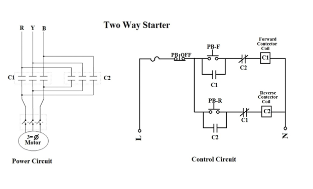
FIGURE: POWER AND CONTROL CIRCUIT OF TWO WAY STARTER
A phase line is taken and is connected to the Overload through its NC point. It is then connected to a push button through its NC point; this push button acts as the Stop button and is referred as PB OFF. One wire from PB Off goes for the connections of first contactor, C1 and a second wire goes for the connections of second contactor i.e. C2. The NO auxiliary contact of the contactor is connected in parallel with a push button through its NO points. This parallel connection is then connected to the NC auxiliary contact of the second contactor, followed by the coil of the first contactor. This is how the connections of both the contactors are made individually. Finally the wires coming out from the coils of both C1 and C2 are connected to the neutral.
WORKING MECHANISM OF TWO-WAY STARTER
There are three push buttons in a Two-way starter. One acts as the Stop button (PB-OFF) and the other two are used to move the motor in forward (PB-F) and reverse (PB-R) directions respectively. As we push the PB-F button it becomes NC from NO and the current starts flowing in the first line of the control circuit. So the coil of the contactor, C1 energizes and becomes conducting. At the same time, the Auxiliary contact of C1 also becomes NC from NO, this way, the contactor holds. We have also connected the NC auxiliary contacts of C2 in this line, along with the coil and NO contacts of C1. But since the C2 is connected through its NC and we are yet to touch the coil of C2, therefore it remains in NC only and continues to be conducting. But the NC auxiliary contact of C1 which is connected in the second line of the control circuit along with the coil and NO of C2 becomes NO. We know that as the coil of the contactor energizes, NO becomes NC and NC becomes NO. So this prevents the current from the entering the second line and energizing the coil of C2. This way only C1 holds at that time and the motor moves in forward direction. Similar mechanism takes place when we push the PB-R button and the motor moves in reverse direction. In the reverse case, current flows only through the second line since here C2 energizes and the NC of C2 (in the first line) becomes NO, whereas the NC of C1 (in the second line) remains to be NC. This system of connection where NC auxiliary contact of first contactor is connected with the coil of second contactor and similarly NC auxiliary contact of second contactor is connected with the coil of first contactor is called Electrical Interlocking. Electrical interlocking is important as it prevents the energizing of the second coil when the first coil has already been energized. So this assures smooth running of the motor in both the directions independently. Electrical interlocking also prevents damage to the motor if someone pushes both the Push buttons (PB-F and PB-R) together. In this case none of the contactors will hold because both the NC auxiliary contacts become NO, so both first and second lines of the control circuit become open. Now, if we wish to stop the motor, we push the PB-OFF button. This push button is initially connected through its NC. So as we push it, it becomes NO from NC which breaks the circuit and supply of relay coil is broken, the plunger moves and the close contact of main contactor becomes open, which finally disconnects the supply of power to the motor.
